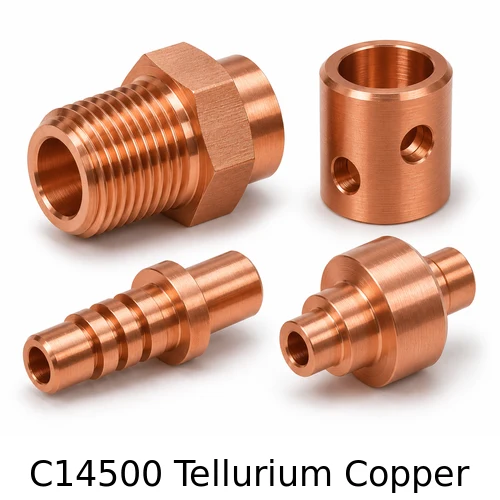
C14500 Tellurium Copper Screw Machine Parts
Rate: US$19.50 per kg
C14500 tellurium copper is a candidate for small repeat-production machined parts when chip control matters and the design still calls for a conductive copper alloy. A typical order might include hollow connector bodies with a tapped end, grooved contact sleeves or threaded adapters with a radial hole. These features create separate chip-clearance and deburring problems. In a small part, even a low burr can interfere with a mating pin, a sealing element or a fine thread. The quoting review starts by establishing which features the assembler will touch, gauge or load.
Tellurium improves the cutting behavior of this copper alloy. The material grade does not establish an equipment current rating, contact life or suitability for a particular joining method. Use the current material specification and certificate for the ordered stock. Tellurium-bearing copper and sulfur-bearing C14700 are separate UNS grades. A design that calls out one of them should use that grade unless engineering approves a substitution in writing. Conex Screws can review the geometry, part quantity, tolerance stack and stock form together when quoting.
Small turned parts suited to review
| Part or characteristic | Drawing and application details | Inspection and quoting considerations |
|---|---|---|
| Coaxial connector bodies | Specify stepped bores, thread position and any face that controls the installed depth of the mating connector. | Establish the turn axis and put a measurable limit on alignment between the bore, thread and external pilot when fit depends on all three. |
| Cross-drilled miniature adapters | Show radial hole position measured from a functional shoulder and define any clocking to a flat or slot. | Inspect the bore intersection for burrs or folded material. Gauge the passage after the last process that could affect it. |
| Grooved contact sleeves | Clarify whether the groove carries a retaining clip, a seal or a fixture used during assembly. | Specify groove width and root diameter with a compatible radius. Review burrs on both edges before finishing. |
| Threaded contact bodies | Mark whether the thread clamps, seals, transmits current or positions a subassembly. Define start and runout from the seating face. | Use the full mating thread callout with class and usable engagement. An assembled sample helps detect interference beyond gauge engagement. |
| Shouldered screw machine parts | A shoulder can act as a stop, a contact face or a locator. Separate the working face from the cutoff side. | Check shoulder position, face runout and clearance at the shoulder corner. Record the actual edges used for measurement. |
How to control repeat production
| Part or characteristic | Drawing and application details | Inspection and quoting considerations |
|---|---|---|
| Small bores | Give the through or blind condition, effective cylindrical length, usable depth and any internal step. | Review drill point and boring bar access before setting the depth. Fine threads can limit visual access to the bore. |
| Live-tool features | A radial hole, key flat or slot may need controlled angular position relative to another feature. | Identify the angular datum and the mating envelope. Qualify the setup using a first article that has every secondary operation complete. |
| Thin walls at an intersection | A through thread, radial hole and groove can all remove material in the same short length. | Review minimum remaining wall in the finished part. Check that a burr removal method does not open the intersection beyond its intended envelope. |
| Stock form and lot | Specify round or shaped bar, temper and the exact material grade on the drawing. | Approve any alternate form that affects grain direction, machining access or available dimensions. Preserve heat or batch traceability as specified. |
| Deburring sequence | Show allowed edge breaks and preserve sharp functional edges where the design requires them. | Choose a method that reaches the intersection. Inspect before and after finishing if handling or plating can change the bore condition. |
Engineering questions for the first article
Will a Swiss-type process help every C14500 part?
A guide bushing can support slender work near the tool. Short parts may suit conventional bar-fed turning just as well. Compare the length-to-diameter ratio, bar straightness, feature access and volume. The agreed process should deliver the drawing and inspection results at the intended production rate.
How do I specify a hole intersecting a thread?
Call out the radial hole diameter and center from the seating face. Show the permitted burr or edge condition at the thread intersection. If a male thread must pass the hole during assembly, include a functional trial with the actual counterpart or an approved master.
Can the design use a finer pitch for a thin wall?
Review minor diameter, load, available wall and repeated engagement together. Fine pitch changes the balance between available material and the mating length. The mechanical designer owns the torque and strip-load criteria. Submit the mating hardware drawing and state the intended number of installations.
What controls part-to-part repeatability?
A stable bar condition, tool life plan and sampling at agreed intervals contribute to repeatability. For critical dimensions define the reporting method and record first and last pieces from each sampled interval if required. Report any lot break that introduces new stock or a changed operation.
Example of a cross-drilled C14500 body
Consider a small cylindrical adapter with an axial bore, a radial cross-hole and a fine external thread. The radial hole begins on a wrench flat. If the flat and cross-hole are defined only by rough orientation in a sketch, the hole can emerge at an edge and leave a narrow wall. The drawing should clock the hole to the flat and locate it axially from a shoulder. Review the remaining material through the bore intersection and thread root using a section model, including the tolerance of the hole center.
The drill entry may be simple to inspect while the hidden exit inside the axial bore is difficult to reach. An approved deburr step needs access to that exit. Where the intersection crosses the path of a mating pin, a functional sample can catch interference that a diameter check alone misses. The inspection plan can specify a bore check after cross drilling, then repeat the relevant fit check after plating or final cleaning. If the process changes, compare the first article to the same approved mating configuration.
Improve small-part yield through feature order
Make the functional diameter while the bar or part is supported where deflection is lowest. There may be advantages to boring and turning the pilot in the same setup, then drilling a radial feature with a suitable tool and re-checking the bore. If a groove leaves a thin ring, review whether subsequent clamping can deform it. A cutoff burr can affect the length or surface contact of the finished part even when every upstream operation is stable.
For production planning, choose the feature that should trigger a tool change before it reaches its limit. A tight thread, bore finish or radial burr can drift earlier than the main diameter. Define a sample frequency and inspection method that can detect the drift in time. When a new bar lot is introduced, retain the traceable lot identification and make an agreed check on the first parts from the new material. This helps distinguish stock changes from tool wear and setup effects.
Compare C14500 with other conductive copper grades
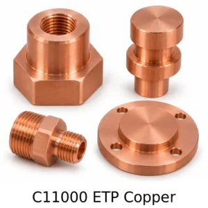
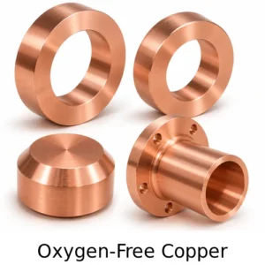
C14500 is tellurium-bearing copper. C14700 is sulfur-bearing copper. Both belong in a material-selection discussion for screw machine parts, with separate specifications, documented availability and engineering approval for a change. C11000 ETP copper addresses a different starting requirement in many power-distribution drawings, and C10100 or C10200 may be called out for oxygen-free material. Compare current certificate requirements and the real manufacturing problem before altering a grade callout. Chemical designations, finish requirements and any validated joining processes can limit which options are available.
Conductivity data depends on the cited grade, condition and source. Compare material-property figures in the same units and under the same reference conditions. For an application with a high-current joint, use the finished contact geometry and approved resistance or temperature-rise test to validate equipment performance. A grade change made to improve chip control can also affect forming, joining, strength or downstream qualification. Ask the design authority to disposition the change before quoting production from substituted stock.
An acceptance example for a narrow groove
For a small retaining groove, show the width between the working faces, permissible root radius and minimum root diameter. A gauge that locates the width at the entrance may miss an internal taper or a fillet that limits full engagement. Provide the mating retaining element and its tolerance if engagement is critical. If a groove is used only for handling, label that purpose to give the machining review appropriate freedom.
How to prepare a drawing for quotation
Send a dimensioned PDF for acceptance and a STEP model for geometry review when available. Identify the current revision on both files. The PDF should distinguish basic, reference and toleranced dimensions, specify units and define precedence when the model and drawing disagree. Share the assembly context if the finished part seats against an insulator, mates with another copper piece or passes through an enclosure. The most valuable information is usually a section through the working axis and a note identifying the features that govern acceptance at receiving.
Mark the expected order quantity, lot size and annual demand separately. Production tooling, inspection and stock planning depend on how the demand is released. A batch of samples can qualify geometry before the full release. If the drawing changes between a sample and production order, state whether the earlier inspection report still applies and list the features affected by the change. Include any quality clauses that carry over to later releases.
Choose the stock specification and condition
A copper grade is a material designation. It does not specify all of the attributes of the starting stock. State the form, temper, material specification and revision required by the contract. Where the drawing cites ASTM B187/B187M for copper rod, bar or shapes, confirm that the grade and stock form are covered by the selected edition and scope. If stock is approved to a different standard, request engineering disposition before material is ordered. Separately identify the requirements for the finished component, including dimensional checks, coating and packaging.
A material test report is most useful when the receiving team can map it to the parts in a container. If traceability is contractual, define whether it must be maintained by heat, manufacturing lot or individual piece, and how identification will be applied. A bag or carton label can protect working surfaces from marking. A permanent stamp needs an approved location away from mating faces, thin walls and tight diameters.
Set up the turning sequence around the working interface
Turned features that share an axis may benefit from production in one setup. A long bore, slot or radial hole can still require an additional operation. Establish which relationships drive the setup before the machining plan is frozen. If a part must transfer to another chuck or a separate fixture, identify the gripping zone and the surface that re-establishes the location. Check whether a previously finished section must be protected against fixture marks.
A part drawing can leave the machining sequence to the supplier while preserving requirements for the result. For qualification, ask the supplier to explain how the operation sequence protects critical faces and how it will respond when tools wear or stock changes. Where sequence is contractual because of an approved special process, put that requirement on the purchase order and identify the conditions under which a change needs customer approval.
Specify bore geometry and tool access
On a blind hole, distinguish total drilled depth from the depth of full cylindrical diameter. If the hole contains a thread, specify full-form thread depth separately from the depth of drill point and thread runout. A counterbore or spotface should have its own dimension from the reference face. Deep narrow passages need sufficient access for measurement as well as for machining. If the application accepts the natural drill point, that allowance can help simplify inspection and production.
For a through bore, give the edge requirement at both ends. A raised burr on the exit face can prevent the part from seating and skew an assembly. If a radial passage intersects the axial bore, establish where the edges may be broken and which intersection surfaces must remain clear. Inspection may combine measurement of the passage with a visual or functional check for blocked flow or snagging, depending on the application.
Use thread callouts a buyer and inspector can verify
Use the thread series, nominal size, pitch and class from the drawing. Unified inch callouts can refer to ASME B1.1 as applicable. A metric M-profile callout uses a metric diameter and pitch and its own tolerance designation. State left-hand thread explicitly when required. For an unusual thread, supply the mating drawing or master and the acceptance method. A drawing that shows only nominal diameter may leave incompatible threads looking interchangeable to a buyer.
Define usable engagement, the clearance at the end and the entry edge. On a blind tapped part, specify how much full-form thread is needed ahead of the runout. On an external stud-like feature, verify that a relief groove does not remove a length needed for engagement. Standard thread gauges check the aspects of the thread covered by their design. Where an installed shoulder or a mating member with its own runout limits travel, add a functional fit check to the inspection plan.
Compare turned surfaces, finish and edge treatment
The surface roughness requirement should identify the parameter, units and working area. When traces can run in more than one direction, specify the direction relevant to the function and the method if it is important for repeatability. Compare the desired finish with what the actual bearing surface or bore can accommodate. A small annular contact pad may leave limited space for an instrument trace, so agree the method before production.
Define where burrs are unacceptable and where edge rounding is constrained. A blanket edge break may be inappropriate on small grooves or edges that establish a working length. Show these as exceptions and identify safe handling edges where a normal chamfer is acceptable. Agree whether small surface marks are cosmetic or restricted by a functional requirement. A photographic limit sample can help clarify a finish specification when visual acceptance matters.
Plan coating around the finished part
Tin, silver and nickel can serve different functions. Specify the coating and any underlayer, thickness and areas to cover on the drawing. Call out surfaces that need masking, any limits on buildup or bridging, and areas used for rack contact if a witness mark matters. Report material and coating requirements separately so the ordering team can distinguish the base copper from the final surface. When the intended process is still being selected, describe the application and ask for an engineering review.
In a simple concentric bore with a uniform deposit on both opposing walls, a coating of thickness t on each wall reduces the diameter by approximately 2t. A corresponding outside diameter increases by about 2t. This geometric estimate assumes uniform coverage and simple cylindrical surfaces. A deep blind hole can plate unevenly, and threads require separate treatment of flank geometry and gauge fit. Verify the finished fit using the inspection method agreed for the drawing.
Agree how critical dimensions will be measured
The inspector needs the same functional datums as the design and assembly teams. Specify what establishes the axis, the face from which axial distances are measured and any feature that clocks a slot or hole. A datum setup should support the part without distorting it. For short or slender features, identify a practical checking method before committing to a tight dimensional tolerance. A dimension that can be machined reliably still needs a method that can distinguish conforming parts.
External diameters can be measured at selected planes, while bores may require plug gauges, internal measuring instruments or coordinate measurements. A go gauge confirms an acceptance condition within its design. It does not report the full bore profile. If taper, ovality, position or axial variation matters, put that geometric requirement on the drawing and agree how to check it. Document the inspection condition when temperature, measuring force or fixturing can change the readings.
First article and ongoing inspection
A first article is most useful when it comes from the intended production material and process route. Ask for a marked-up drawing with numbered characteristics and a report showing actual values for the agreed dimensional features. Give a separate row to any functional test, material verification or coating acceptance criterion. Review the lot certificate and finished inspection together so the identified sample can be tied to its stock and operation history.
Agree sampling and records before production. Identify any features subject to complete inspection, any dimensions to record at process intervals and the method for addressing a suspect batch. If process capability is requested, define the study conditions and the minimum data set. A first article shows an inspected sample at a point in time. Ongoing records and change control show whether the agreed process continues to deliver the same features during repeat orders.
Receiving and handling of machined copper parts
Decide how parts are cleaned after machining and after any coating. Bores, slots, blind recesses and intersecting holes can retain chips or processing fluid. Give a cleanliness test or an acceptance sample when the allowable condition is important. Define whether the supplier may use corrosion protection or whether the component will go directly into a customer cleaning, soldering or assembly step. Incompatible protective products can create additional preparation work at receiving.
Protect dimensions that are easy to mark or distort. Separate sharp projections from thin walls and keep the working faces from rubbing against one another. Discuss trays, dividers, individual sleeves or simple bulk packaging in light of the size, surface condition and handling route. Identify the lot, drawing revision, order number and quantity on the outer label when requested. Where the parts are supplied in groups for a matched assembly, give each group a distinct identifier.
Common RFQ questions
Can Conex Screws quote from a sample?
A physical sample can help identify the machining route, mating conditions and finish. Supply a drawing or approve a controlled drawing before production. Surface measurements on the sample may include wear, distortion or coating, so identify the accepted nominal values and state whether a replacement part must mate with legacy hardware.
Can I request both metric and inch information?
Yes. Use one unit system as the controlling dimension set and mark the other as reference where appropriate. An exact unit conversion can produce a precision that the original tolerance did not intend. Keep the thread family in its native designation. If the product goes into a mixed-unit assembly, share the mating drawing with the enquiry.
How are tolerances and lead time confirmed?
Review is based on grade, part geometry, tolerances, inspection, lot size and the stock or tooling needed for the order. Highlight the dimensions tied to assembly or electrical performance. Conex Screws can then review measurable acceptance methods, production sequence and lead time with the buyer at quotation.
How does the per-kilogram rate relate to ordering?
The listed rate for this product family is US$19.50 per kilogram. Send the drawing and requested quantity for a written quote that identifies the order basis, finish, inspection and shipping terms. If your purchasing system orders individual pieces, request the agreed piece-weight basis and price presentation for the quotation.
Can I specify a material grade different from the examples?
State the UNS designation, specification and temper and provide the target application. Quote review can check grade and stock availability, cutting access and inspection. Procurement should approve the exact designation against the drawing before any material is released.
Which checks apply before and after plating?
Use before-coating checks where they control machining or establish a baseline. Set finished-part acceptance against the agreed drawing and functional gauges. Where access is limited, agree coating measurement locations and test frequency at quote stage. Provide an approved mate for assembly-sensitive interfaces when useful.
What should a quote package include?
Provide the product drawing, revision, part quantity, target delivery, material grade and temper, critical tolerances, finish, packaging and any required reports. Include the mating drawing or assembly section if available. Attach any first article forms and identify requirements that have to be agreed before materials are procured.
Turn an assembly requirement into an inspection characteristic
Start with a sentence describing the risk. A part that stops short at assembly, rocks under a clamp or loses engagement during handling needs a different check in each case. Identify the feature in the drawing section that controls the outcome. Write its acceptance as a measurement with a datum or as a test with a controlled mating condition. Avoid a note that relies only on interpretation, such as asking for a good fit, when the requirement can be described in a drawing or test plan.
Create a short list of characteristics that govern release. Review them with the receiving team so the supplier knows which actual values and documents to include. A first article can document the relationship between related features, and ongoing checks can focus on the measurements likely to change during production. If a tolerance is changed in the drawing, record which master sample or gauge revision applies. When the fit depends on a downstream operation, agree whether the receiving inspection verifies an intermediate condition or the finished assembly.
Manufacturing and purchasing checklist
Before ordering, confirm that the drawing names the component and clearly identifies the part revision. Verify that the quotation records the same material and the same delivery condition. Ask for an approved sample or dimensional report if the geometry is new, if a new stock size must be sourced or if the same part number was previously ordered with a different finish. Include an approved deviation on the order when engineering has accepted an exception. Identify the point at which approval expires if the deviation applies only to samples.
Set the information required for future reorders. Preserve the drawing number, revision, material requirement and the inspection or packing conditions that define the part. Where samples use a process different from the intended production route, agree what evidence the production process needs before release. Where a surface has multiple requirements, identify their order of precedence and the areas to which they apply. This gives purchasing a repeatable order description and gives the incoming inspector a set of clear checks.
Define the finish and limits for visual acceptance
A finished machined surface may have normal turning marks visible under directional lighting. When appearance affects assembly or end customer acceptance, state the lighting, viewing area and permissible marks, or reference approved samples. On a concealed body, machining marks outside the working area may matter only where they create a burr or change the dimension. On a mating diameter or face, the same marks can affect seating or friction. Set the acceptance area on the drawing and identify any surfaces where contact from packing material is restricted.
Agree how witness marks are handled. A rack contact can leave a small mark after plating, and a fixture can mark a part during transfer. Restrict marks on the functional zone and establish any agreed acceptable areas before the process is approved. Keep the visual limits separate from quantitative checks for dimensions, roughness and coating thickness. When a part is intended to be further machined, specify which surfaces remain on the completed assembly and which are left as extra stock.
Material, thread and product references
- Copper Development Association C14500 data
- Copper Development Association C14700 data
- Precision Swiss machining
- ASTM copper rod, bar and shapes specification
- ASME Unified inch screw thread standard
Send your drawing to Conex Screws
For a quotation, provide your drawing revision, material designation, finish, order quantity and any inspection documents. Include the mating geometry where fit matters. Conex Screws will review the manufacturing and acceptance requirements with your engineering or purchasing team.
Email your drawing for a quote at sales@conexscrews.com
Explore all Copper Screw Machine Parts and CNC Turned Components